


This section provides a brief overview of simplified GPS, a summary of the errors associated with the measures, and the various types of differential corrections.
GPS – Operation
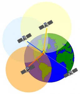
The Department of Defence (DoD) US operates 24 hours a day, a global positioning system (Global Positioning System or GPS) reliable at all temperatures. NAVSTAR (NAVigation Satellite Time And Ranging), the original name of this positioning tool and geographic navigation, includes an official constellation of 24 satellites (plus a few in active reserve) in orbit around the Earth at an altitude of about 22 000 km.
Basic Principle
 These satellites transmit various coded information to GPS users on different UHF frequencies (eg, C / A code L1 at 1575.42 MHz).
This information allows the equipment of a user to calculate the range to each satellite. GPS is essentially a timing system – the radii are measured in minutant the time required for a GPS signal encoded to achieve the user’s GPS antenna. To calculate a geographic position, the GPS receiver uses a complex algorithm incorporating satellite coordinates and range to each satellite. Receiving four or more of these signals allows the GPS receiver to calculate the coordinates in three dimensions. The pursuit of only three satellites reduces the positioning of two-dimensional coordinates (horizontal and vertical fixed). The GPS receiver calculates its position relative to a central phase of the GPS antenna. The latitude, longitude and altitude of the antenna are measured according to the most recent revision (G-1150) of the ellipsoid of the World Geodetic System 1984 (WGS 84). (Note that the current revision G-1150 differs from the original establishment of the WGS 84. See “About Datum” in the menu “Understanding SBAS”).
GPS services
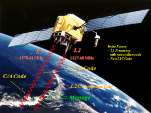
The accuracy of the position presented by the GPS depends on the type of service and equipment available. For security reasons, there are two GPS services: Standard Positioning Service (SPS) and the Precise Positioning Service (PPS). SPS uses a modulated code in the measurement signal known as the C / A code. The Department of Defence (DoD) of the United States reserves the SPP to the use of its staff and authorized partners. PPS uses a different code than the SPS, known as P code, whose resolution is higher than the C / A code. The DoD provides the SPS free all over the world, to all civilian users.
Currently, a standalone GPS receiver can achieve an accuracy of about 10 to 15 meters, depending on the sophistication of the GPS engine. For several applications for positioning and navigation, this level of precision is insufficient, and differential techniques must be used.
 Sources of error and need for differential correction
There are various sources of errors that affect the accuracy of GPS receivers, and various methods of compensation of these errors.
Error Sources
In the past and to maintain a strategic advantage, the DoD US artificially degraded performance SPS so that the positioning accuracy was limited to 100 meters in 95% of cases. This intentional degradation was called SA (Selective Availability). The effect of SA was reduced to zero since the middle of 2000, and was officially “off” (permanently) in 2007.
The main sources of errors that now degrade GPS performance include atmospheric errors, satellite geometry, multipath, tracking time and orbital errors satellites.
• Atmospheric Errors:
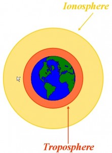
Atmospheric errors are the sources of the most common errors for GPS. As the satellites are in orbit at about 20,000 km around the earth, the GPS signals must pass through the layers of the ionosphere and troposphere before reaching the receiving antenna. The ionosphere is a collective term identifying various layers of ionized particles and electrons located at altitudes from 80 to 250 km in the atmosphere. Ionization is especially caused by short wavelengths of solar radiation (X and ultraviolet rays) in the course of the day. Ionospheric activities have the greatest impact on the accuracy of GPS.
Differential correction greatly compensates for atmospheric errors.
• Geometry of satellites:
As the receiver uses triangulation of GPS signals to determine its position on the ground, more satellite geometry in the sky is precise, resulting triangulation is accurate.
The effect of satellite geometry on the position error is called DOP (Dilution of Precision for or Dilution of Precision). The GPS receiver constantly calculates the DOP value based on satellites currently used to determine its location. The better the geometry (well distributed satellites in the sky), the lower the DOP value. If all satellites are in the same area of the sky or are blocked by buildings, mountains, etc., geometry will be poor and the computed DOP value will be high.
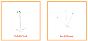
The HDOP values VDOP, PDOP, TDOP and GDOP are respectively weakening Horizontal accuracy Vertical, Position (3D), Time and Geometric.
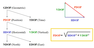
No fixed indication establishes what a “good” or “bad” DOP value. Knowing that the ideal DOP value is 1, each application requires a different precision and allows higher DOP values. Usually 1-2 is excellent, 3-4 is good, 5-7 is acceptable and 8 or more is poor. However forestry companies that only require precision of about 5 m and seeking increased productivity accept a PDOP as high as 8 to 12. Differential correction will not compensate for the errors of DOP. The DOP value is calculated by the receiver, most GPS software offer filters to prevent operation or recording when the DOP value reaches a predetermined threshold.
• Multipath:
This is a propagation phenomenon that that the radio signals reach the antenna by two or more paths. The causes of these multipath include atmospheric pipe, reflection and ionospheric refraction and reflection of a body of water, mountains, trees or buildings.
Differential correction will not compensate for errors caused by multipath. Certain precautions can reduce the sensitivity of the GPS antenna to the signal reflections, such away reflective structures such as buildings.A combined receiver / high-end antenna will better reject multipath, while a less expensive device tolerate a greater number of multiple paths.
• Timing Errors and satellite orbit:
GPS satellites have very precise atomic clocks and follow certain orbits. But excesses are inevitable in both the clock and in the orbit, and even a very low drift can cause errors in the receiver on earth. Although the clock and orbit can not be adjusted, the offset is calculated by the terrestrial component of the GPS and sent to the satellites. The satellites then transmit the data and clock ephemeris to the user.
There may be a delay between the time offset occurs, and when it is calculated and issued.
According to the differential correction used (local or global), the effects of orbit and timing errors can be largely compensated.
What is a local differential correction? (LBAS)
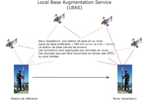
The differential local GPS, DGPS most current, is essentially a differentiation process which eliminates sources of GPS positioning errors and improves its integrity. This type of differential correction is often called Local Area Augmentation System (LBAS – Local Based Augmentation System), corrections are calculated from a reference station (where the antenna is installed at a known point), and applied to GPS Mobile either in real time or in post-processing software. There are several methods of local differential correction:
• Conventional real-time differential correction:
This is the most common way to correct GPS errors in real time, the corrections being sent by the reference station to the mobile GPS via a communication equipment. The conventional differential correction in real time using the measurements of the scope of the C / A code and associated connections. The carrier phase corrections are not used with this type of differential technique.
• Post treatment :
This method is often used when a higher than that offered by conventional differential correction accuracy is needed, or a conventional form of real-time correction is not available in the area where the mobile GPS is used. Depending on the physical receiver and the methodology used for post-processing, the precision achieved can play a few centimeters to a few millimeters. A range of third-party software packages are available for post-processing of the raw GPS measurements.
• RTK – Real Time Kinematic:
This method uses more sophisticated techniques to solve the number of wavelengths between the satellite and the user, to provide centimeter-level (or lower) in real time. For this technique you need a receiver and high-end antennas and an internal operating software to calculate precise positioning.
What is a spatial augmentation system (SBAS)?
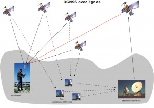
SBAS is a type of newer and different differential correction. It incorporates a modular architecture, similar to that of GPS, including a land component, a space component and a user component:
The land component includes reference stations, processing centers, communication network and ground station navigation (NLES – Navigation Land Earth Station).
The spatial component includes geostationary satellites (such as EGNOS currently uses Inmarsat transponders).
The user component includes the user’s equipment, including a SXBlue II GPS receiver and antenna. In a SBAS a separate correction is available for each source of error rather than the total effect on the scope of measuring the user’s equipment. The result is a more consistent system performance regardless of geographic location relative to the reference stations. More particularly, the SBAS calculates the following distinct errors:
• ionospheric error
• GPS Timing Errors
• Errors of GPS satellites orbit
To understand how a spatial augmentation system (SBAS) like WAAS / EGNOS / MSAS / GAGAN, we first present you the conventional method of differential correction in real time, as well as factors affecting the accuracy of a local DGPS. (Note that this section does not deal with the differential correction of the carrier phase).
 GPS-RTKSystème local increase (LBAS)
A conventional DGPS involves installing a reference GPS receiver whose antenna is placed at a point whose coordinates are known. This receiver performs the distance measurements in real time, to each of the GPS satellites. The measured range includes errors in the system. The receiver of the reference station calculates the true scope without mistakes, knowing his own details and those of each satellite. The difference between the known range and the measured range from each satellite represents the range of error. This error is the number that must be subtracted from the measurement of the distance of each satellite to correct errors in the system. The reference station transmits corrections to the error range of the remote receivers in time réel.Le remote receiver corrects its satellite range measurements using these differential corrections, resulting in a much more precise positioning. This is the predominant strategy DGPS used in the majority of real-time applications. A positioning that uses the corrections generated by a beacon, for example, will give a horizontal precision of 1 meter to 5 meters with a 95% reliability based on the quality of the GPS receiver used. By the same principle, DGPS systems most sophisticated short range (10 to 15 km) can achieve centimeter accuracy using a carrier phase. We speak in this case of an RTK system rather than a DGPS.
System space increase (SBAS)
The Federal Aviation Administration of the United States has developed an extensive augmentation system (WAAS – Wide Area Augmentation System) in order to ensure very precise positioning in the aviation industry. In addition to providing a high quality service and accuracy in the industry, this system is available to all users and civil markets in North America and Central America. This service is part of the broad category of space-based augmentation system (SBAS).
After a successful trial 21 days August 24, 2000, the US Federal Aviation Administration announced that its extensive augmentation system (WAAS) is now operating 24 hours a day, seven days a week. Tests have shown that this signal is accurate and reliable. Since its commissioning on 10 July 2003, WAAS has undergone some changes in its constellation and its coverage of satellites (PRN 122 and PRN 134 replaced with 135 and 138 new locations, and by adding monitoring stations land in Canada and Mexico in September 2007).
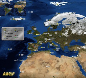
Other government agencies have followed suit and developed SBAS compatible to their respective geographical areas. In Europe, the European Space Agency, the European Commission and EUROCONTROL have jointly developed the European Geostationary Navigation Overlay Service (EGNOS). EGNOS is now fully deployed and is in pre-operational phase. The system must be certified safe for saving life before being fully operational. In addition, on 28 June 2007, the European Space Agency and the Agency for Air Navigation Safety in Africa and Madagascar have signed a collaboration agreement with the aim to use satellite navigation to improve safety air traffic over the African continent.
In Japan, the multifunctional Satellite Transport (MSAS – Satellite-based Augmentation System) was deployed by the Civil Aviation Bureau of Japan. The successful launch of MTSAT-1R and MTSAT-2 satellites were followed by system integration for land MSAS and MTSAT by sending test signals from the MTSAT. The purpose of the transmission of the test signal was designed to optimize system performance and verify that the information meets the increased requirements for safety and performance. As these tests are successful, the MSAS was commissioned for use by aviation September 27, 2007.
In India, the Indian Space Research Organisation (ISRO) and the Indian airport authorities have successfully completed the final acceptance test of the GPS Aided GEO Augmented Navigation system (GAGAN) as announced November 20, 2007 by the Raytheon Company. This final acceptance test is completed, India is now moving towards the next phase of the program, which will extend the existing ground network, add redundancy, and produce analysis and certification documentation for the commissioning of the aviation safety. The satellite Inmarsat 4F1 has been used for acceptance testing of the system. Pending the launch of its own communication satellite, GSAT-4 the (planned for June 2009), the Indian ISRO has stopped issuing GAGAN test signals.
China has a similar program for a SBAS, the service named Chinese Satellite Navigation Augmentation System (SNAS).
Our range can receive the correction data for all SBAS compatible.
Operation
SBAS incorporates a modular architecture, similar to that of GPS, including a land component, a space component and a user component:
The land component includes reference stations, processing centers, communication network and ground station navigation (NLES – Navigation Land Earth Station).
The spatial component includes geostationary satellites (such as EGNOS uses Inmarsat transponders).
The user component includes the user equipment, eg Arrow GNSS receiver and antenna.
The software architecture is based on SBAS state. This means that a separate patch is available for each source of error rather than the total effect on the scope of measuring the user’s equipment. This allows to more effectively manage the problems of spatial de-correlation with some other techniques, resulting in a more stable system performance regardless of geographic location relative to the reference stations.
More particularly, the SBAS calculates the following distinct errors:
- Ionospheric error
- GPS timing errors
- Orbit errors GPS satellite
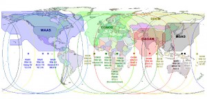
The figures below show the ground segments of the WAAS, EGNOS and MSAS respectively. In 2007, thirteen monitoring stations were added to the existing WAAS network, increasing coverage of ionospheric SBAS constellation.
The locations are shown in red: 4 in Alaska, four in Canada and 5 in Mexico. WAAS ground segment EGNOSSegment terrestrial ground segment MSAS (end 2007)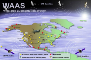
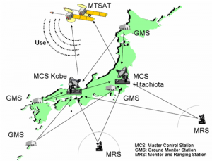
Ground Segment MSAS
Provided the SBAS reference station network can continue a GPS satellite corrections orbit and timing will be provided to this satellite. Ionospheric corrections for this satellite are only available if the signal passes through the ionospheric map provided by SBAS (eg WAAS ionospheric map covers the whole region of North America and Central America).
For example, if a satellite is south of your current position to a lower elevation, the breakthrough point of the ionosphere will be located much further south of your position because the ionosphere is at an altitude of about 60 km. There must be sufficient coverage of ionospheric map beyond your position so ionospheric corrections go to all satellites.
To improve the information provided by SBAS, GNSS Arrow has the unique ability to scale ionospheric information beyond the broadcasting schedule. This feature expands the geographic coverage area usable SBAS system.
Information signal
A SBAS transmits the correction data on the same frequency as GPS from a geostationary satellite (space segment), allowing use of the same receptor used for GPS. Another advantage to this transmission SBAS on the same frequency is that only one antenna is required.
Reception
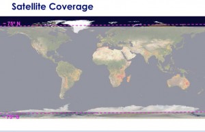
As SBAS transmits in the L band, the signal requires a line of sight like the GPS in order to maintain the acquisition. Choose eg WAAS. Currently, two communication satellites transmit WAAS data for public use. Given their location, these satellites can look down on the horizon, depending on your location on Earth. In areas where satellites appear low on the horizon, they are more easily hidden by terrain, trees, buildings or other objects, which can result in signal loss. The more you are away from the equator and the satellite’s longitude, the satellite will seem more low on the horizon. Fortunately, the COAST technology alleviates this problem by maintaining system performance for a relatively prolonged loss of signal SBAS.
Comprehensive coverage of SBAS
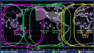
The figure below illustrates the current global coverage of SBAS. This figure provides a rough signal coverage for each SBAS constellation. Although there are geographic coverage at higher altitudes, the practical use of SBAS is limited to environments where a relatively constant line of sight of satellites by the GNSS Arrow system is available.
Coverage of SBAS
The following map shows the sky coverage of each SBAS constellation. For WAAS, EGNOS and MSAS, image grids are the actual grids, without extrapolation. The grid shown for GAGAN was recorded by a GNSS Arrow during the final stage of acceptance testing and is not the official gate of the Indian authorities.
Extrapolation de la carte ionosphérique SBAS
To improve the ionospheric map provided by SBAS, GNSS receivers Arrow extrapolate a sky map larger than that emitted, thus expanding its effective coverage. This allows to use the GNSS Arrow successfully in areas where competitive products can not function. For example, the extrapolation improves coverage of the northern part of South America for WAAS signals, and the northern part of Africa for EGNOS signals, etc.
It should be noted that the process of estimating the ionospheric corrections beyond the issue of SBAS will not be as accurate as if the SBAS map itself was more extensive. This difference can cause minor accuracy degradation. The figure below illustrates the actual ionospheric emission of WAAS and EGNOS signals and the extrapolated release. As can be seen, the extrapolated grid extends beyond the actual emission in all directions, effectively improving coverage.
Error Handling – Differences between LBAS and SBAS
Besides weakening the accuracy and multipath (errors that can not be resolved by a differential correction), many factors can affect the positioning accuracy which can be expected of a DGPS system. The most important of these influences include:
Distance between the remote user and the reference station (atmospheric errors and orbit)
How old is the differential corrections received
Weather conditions at the position of the base station and the remote user
Quality of the GPS receiver used at the reference station and the remote stations
Close to the reference station
In an LBAS, the distance between the remote user and the reference station can sometimes be considerable, especially if DGPS beacons 300 kHz are used. Therefore, some errors associated with GPS reference station are somewhat different from those associated with the remote location. This error can cause a spatial decorrelation positioning offset relative compared to absolute coordinates of the remote receiver. This offset can reach one meter per 100 km (62 miles) away from the reference station and the remote receiver.
The causes of decorrelation are:
• Orbit Errors GPS satellite (important)
• ionospheric errors (may be higher depending on the level of activity)
• tropospheric errors (least important)
The orbit errors GPS satellite are usually more severe in the case of local differential systems like beacons. The decorrelation effect is such that the satellite orbit error is projected differently on reference receiver range measurements and remote receiver. As the distance between the receivers increases, the error orbit does not project the same way about scope, and extent of differentiation process does not completely cancel. SBAS networks that use multiple reference stations can more accurately calculate the orbit of each satellite carrier. The resulting correction is geographically independent, so that a very low-correlation occurs with respect to the positioning in the network.
The ionosphere and troposphere causing both measurement errors in the signals received by the GPS. The troposphere is the wet portion of the atmosphere closest to the ground. Because of the humidity, the refraction of the GPS signals at lower altitudes can cause distortion of the satellite measurements. The source of error is easily modeled within the GPS receiver and does not present a serious problem.
The error caused by the ionosphere is more important, however, and is not easy to fix. The ionosphere is the charged layer of the atmosphere responsible for the aurora borealis. Charged particles from the sun ionize this portion of the atmosphere, resulting in an electrically active layer of the atmosphere.
This electrical activity night to GPS signals that penetrate this layer, affecting the spans measured. Making it difficult to remove the effect of the ionosphere is that changes daily, even hourly, because the solar cycle of 11 years and the rotation of the earth. During summer 2001, the solar cycle reached its highest point in 11 years, and we noted a gradual cooling of the ionosphere in the years that followed, accompanied by a smaller ionospheric activity. Removal of the ionospheric effect depends on the architecture of the differential network. The radiobeacon, for example, use a more conventional approach as WAAS or SBAS in general. The radiobeacon use a single reference station, which provides GPS error corrections in real time based on measurements taken at the location. It is possible that the state of the ionosphere is different to the position of the remote user and to that of the single reference station.
This can produce a source of error that is not fully corrected and which could degrade the positioning accuracy, the more distance there is between the reference station and the remote user. The SBAS (WAAS, EGNOS, MSAS, GAGAN, etc.) use a different approach, instead serving as a reference station network in strategic locations to take measurements and model the ionosphere in real time. The updates of the ionospheric map is continuously sent to correct the position of the user as the ionosphere changes. Compared to the use of a DGPS beacon, the effect of the proximity to a single reference station is minimized, resulting in a more consistent performance of the system in all locations in the network.
Delay corrections
The time differential corrections to a lesser extent affects the accuracy of positioning the remote receiver as the magnitude of the SA was reduced to zero in 2000. The delays depend on the following:
The time required for the reference station to calculate the corrections
The flow of the radio link
The time it takes the signal to reach the user
The time required by the remote differential receiver for demodulating the signal and transmit it to the GPS receiver.
Data loss during reception problems
Most of these require time less than one second, although in some cases, depending on the amount of information transmitted, a total period of three to five seconds may occur. The effect of these delays is mitigated by the COAST technology incorporated in the GPS Arrow. This technology is particularly useful when DGPS signal loss when the age of corrections increases every second of signal loss.
GPS Receiver Quality
The quality of the GPS receiver dramatically influences the accuracy of the positioning. The low-end GPS, like many affordable portable and fixed receivers usually have a horizontal accuracy of 3 to 10 meters in 95% of cases. The accuracy of a given product depends on receiver performance characteristics in question. The most accurate GPS receivers can achieve sub-meter horizontal accuracy in 95% of cases using DGPS transmissions in real time. The range of GPS Arrow is in the latter category.
ATLAS differential is expanded multi-constellation service using satellite broadcast techniques. It Provides a differential correction GNSS worldwide and correcting all the constellations (GPS, Beidou, GLONASS, Galileo -futures versions-) in a format made way for the required accuracy.
Operation
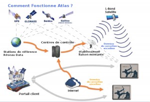
![]() Le ATLAS service generates corrections in your GNSS receiver optimized for the position of the user. EOS supports the Atlas Service output both corrections RTCM-104 high quality for external use, and differentially corrected data on latitude, longitude and altitude in NMEA format. The figure below illustrates the operation of the system.
Le ATLAS service generates corrections in your GNSS receiver optimized for the position of the user. EOS supports the Atlas Service output both corrections RTCM-104 high quality for external use, and differentially corrected data on latitude, longitude and altitude in NMEA format. The figure below illustrates the operation of the system.
• GPS Satellites
• Multiple reference stations • Sending GPS corrections by terrestrial communication network
• Network Control Center, where data corrections are checked and prepared for shipment by uplink
• Geostationary satellite L-band
• Typical coverage geostationary satellite L-band
• Data received corrections and applied in real time
Several services are available:
• H10 Service: 4-5 cm accuracy RMS (8 cm 2DRMS – 95%)
• Service H30: 30 cm accuracy RMS (15 cm 2DRMS)
• H100 Service: sub-meter, 50 cm RMS (1m 2DRMS)
Subscriptions can be taken by the month, the year, as desired.
When asked “what is the reference frame used by GPS? “The answer is inevitably” WGS 84 “. But when asked which version of WGS 84, the answer is not as obvious. In addition, GPS, SBAS (WAAS, EGNOS, MSAS, GAGAN, etc.), Omnistar, radiobeacon, local reference station, etc., all use different datums or frameworks. It is very important to understand the differences between the various implementations within a specific datum, and to ensure that the maps and GPS data is the same version as the datum used.
GPS and history of the evolution of the WGS 84

(The English text in italics comes from the following source NGS: http://www.ngs.noaa.gov/faq.shtml#WGS84)
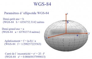
WGS 84 (or 84 SGM) is the World Geodetic System 1984. This is the framework used by the Department of Defence (DoD) of the United States and is defined by the National Geospatial-Intelligence Agency (NGA) (formerly the National Imagery and Mapping Agency) (formerly Defence Mapping Agency). The DoD uses the WGS 84 for its positioning needs, mapping, navigation and surveying, including the orbits of “dissemination” and orbits “precise” in his GPS. WGS 84 was defined in January 1987 using Doppler satellite surveying techniques. He served as a reference framework for the transmission of ephemeris (orbits) from 23 January 1987.
This initial version of WGS 84 is called WGS 84 (original).
At 0000 GMT January 2, 1994, the accuracy of WGS 84 was upgraded with GPS measurements. The official name then became WGS 84 (G730) since the upgrade date coincided with the beginning of the week 730 GPS. It has become the reference framework for the distribution of orbits June 28, 1994.
At 0000 GMT 30 September 1996 (the beginning of the week 873 GPS), WGS 84 was redefined again and aligned more precisely on the International Terrestrial Reference Frame (ITRF) 94 of the International Service for Earth Rotation Service (IERS). He was then called WGS 84 (G873). WGS 84 (G873) was adopted as a framework for broadcast orbits January 29, 1997.
On 20 January 2002, the latest realization of WGS 84, called WGS 84 (G1150) was adopted and the current version. This achievement is based on the ITRF 2000. Between the first implementation of the WGS 84 (original) and the current review, there may be differences in the 1 to 2 meters. In North America, we can use the online conversion tool datums
The following explains why there has been reference for change for GPS orbits.
GPS and the International Terrestrial Reference Frame (ITRF)
GPS orbits are calculated from data collected by a global network of receivers coordinated by the International GPS Service (IGS). The accuracy of GPS orbits depends on several factors, including the accuracy of the coordinates data collection sites. The earth’s surface is not smooth and rigid like an eggshell. It is made of several sections, or plates, which are slowly moving in different directions and at different speeds in a process called crustal movement. Scientists study these movements for several reasons. In particular, they want to know where land masses are located relative to each other, and where they are heading. As IGS sites are located on these crustal plates, we need to assess where the sites are located when the data is collected.
The International Earth Rotation Service (IERS) periodically calculates the sites of the positions on a given date. The sites define the IERS, the International Terrestrial Reference Frame (ITRF), and date sets the time. The IERS also computes the movements (or velocity) of the sites to determine with some precision where they will be in a “near” future. The IRTF is a norm accepted internationally, and presents the geocentric reference system currently most accurate available.
Over the sites of operation duration, the better the estimate of their position and their velocity, and the orbits are accurate.
GPS and SBAS are both based on the reference frame ITRF 2000, with the following difference:
GPS has fixed the time in January 2002 (in other words, for GPS, the crustal motion of the earth has stopped since 2002 until the next review)
SBAS (WAAS, EGNOS, MSAS, etc.), by cons, recalculates the location of earth stations regularly (almost every year) and predicted (or projects) their future velocity for a few months or up to the middle of the year next.
GPS coordinates and map datum
When a GPS receiver is used in standalone mode (without differential correction), the coordinates are transmitted in WGS 84 (G1150), the current GPS reference. When using the following differential corrections:
SBAS: coordinates from a GPS receiver are in ITRF 2008 (current epoch)
Atlas: the coordinates from a GPS receiver are in ITRF 2008 (current epoch)
A local reference station (real-time or post-treatment): the mobile will follow the datum of the coordinates used by the reference station
Postprocessing online PPP (point precise positioning) Canada: choice Nad83 (CSRS98) or ITRF 2008
Local datums have also evolved elsewhere. For example in the US, NAD 83 (North American Datum of 1983) was originally equivalent to WGS 84. Since then he has followed his own path and now has various qualifiers NAD 83 (CORS 96) or HARN. Canada also migrated from NAD 83 (original) to NAD 83 (CSRS 98)
http://www.geod.nrcan.gc.ca/publications/papers/abs6_e.php
Fortunately, the recent revision of local datums are related to a revision ITRF, allowing the use of 6, 7 or 14 transformations settings. It is important to ensure that the data collection software in the field or GIS / topographic office software supports various revisions and datum transformation parameters that are current.
Useful references on the datum
International Terrestrial Reference:
http://itrf.ensg.ign.fr/
Service International Earth Rotation and Reference Systems:
http://www.iers.org/
Canada
Canadian Spatial Reference System (Natural Resources Canada)
http://www.geod.nrcan.gc.ca/index_e.php
online conversion tool TRNOBS Natural Resources Canada:
http://www.geod.nrcan.gc.ca/tools-outils/
(Provides the processing parameters used)
Article – Realization and Unification of NAD83 in Canada and the United States through the TRF:
http://www.geod.nrcan.gc.ca/publications/papers/abs6_e.php
United States
Horizontal based positioning time, NGS transformation tool online:
http://www.ngs.noaa.gov/cgi-bin/HTDP/
Article – Transformation of the positions and velocities between the International Terrestrial Reference Frame (ITRF) 2000 and the North American Datum of 1983 (NAD 83):
http://www.ngs.noaa.gov/CORS/Articles/SolerSnayASCE.pdf
Article list of the NGS website:
http://www.ngs.noaa.gov/CORS/Articles/
The advantages of a modular system
Use of SBAS (Satellite Based Augmentation System) for real-time differential corrections has become common since the coverage and reliability of the system have validated summers. For a better understanding of SBAS (WAAS, EGNOS, MSAS, etc.) or OmniSTAR service please look “understanding the SBAS”
All GPS sold in the market are normally consistent SBAS. But the Eos Arrow receiver is specifically developed for improved performance in the GPS / SBAS system for industry and GIS applications, at a very competitive rate.
What makes the difference? Why the series Arrow Eos Positioning System is unique?
![]() SBAS receivers use to its full potential and as the sole source of differential correction for a DGNSS day. We invite you to read below the key benefits of this revolutionary receiver:
SBAS receivers use to its full potential and as the sole source of differential correction for a DGNSS day. We invite you to read below the key benefits of this revolutionary receiver:
– A sub-meter to centimeter solution without post processing
– A precision and unparalleled performance with SBAS
– Accuracy and performance inigalée worldwide With ATLASTM.
– A flexible modular system
– Options for greater accuracy
– A price ‘low cost’ for its acquisition and maintenance
– Utilsation GPS, Glonass, Galileo and Beidou (reserved)
Sub metric solution without post processing
Why Eos Arrow require no post processing?
Their strength is the ability to maintain a DGNSS position when the SBAS (WAAS, EGNOS, MSAS, and compatible Atlas) is hindered for any kind of obstruction (high canopy). SBAS signals are of the same nature as the GPS signals (that is why the GPS antenna receives GPS and SBAS parallel signals), and therefore subject to the same types of obstruction. The problem is very simple:
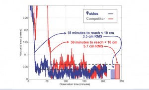
When there is no differential signal, there is no DGNSS … However, the Arrow is capable of maintaining a sub metric precision for about 40 minutes after the loss of the corrected signal.
They not only collect the maximum age of the differential correction input, but it anticipates and predicts, through sophisticated, patented algorithms and proven in the field, how the ionospheric conditions, GPS time and ephemeris evolve the weather. This proprietary technology allows not to waste time with post processing!
In addition, the Eos Arrow offers not only two SBAS channels dedicated, high sensitivity, but also uses satellites SBAS to its position (i.e. as Outer satellite ‘)
With the Eos Arrow, you are free to meet in real time all the time!
Will this technology also work in forestry?
![]()
Absolutely and that’s what makes EOS Arrow’s reputation thanks to its unparalleled reception under trees. You will not have a sub metric precision all day, but you will have a DGPS whole day without post processing solution. The Arrow, with its increased real-time ability, proved to be, if not better, in any case equivalent to other receivers on the market, who needs a post processed signal.
The DGNSS receiver … he works there or you work!
Does this technology accept another source of differential correction?
Yes, that is his strength.
Eos Arrow can operate in DGPS, DGNSS, RTK, anywhere in the world.
Does the sub-meter post-processing is more accurate than realtime?
Not in the case of the Arrow receiver. Submeter for work of quality, using a smoothing of the phase, the accuracy of Arrow in real time with SBAS will be equivalent to the best post processed receiver market.
Free environments in all multipath, methods of post processing on the stage with a floating or fixed ambiguity resolution will yield results between 15 cm and a few millimeters. In these cases, data collection is different from the ‘sub-meter’ and requires initialization and a time for the longest collection and a specific software for processing pst on the stage. for such solutions, look s.v.p to the next section …
Precision and unparalleled performance with SBAS.
![]()
Because professionals need clarification on which they can rely, EOS has developed the series of Arrow to get a precision of 60 cm with free signals WAAS, EGNOS, MSAS and compatible signals, as well as services Atlas.
This accuracy is expressed in 2DRMS (95% of points in these accuracy values)
In HRMS or RMS (average deviation of the point cloud with 67% on average), the equivalent of 30 cm RMS.
In CEP (Circular Error Probable, 50% of cases), while the EOS Arrow has an accuracy of 25 cm.
And yes … using SBAS signal alone!
If you are not convinced, we give you an appointment and we will help you in your efforts.
Is the SBAS is accurate and reliable?
SBAS is quite accurate (for example, see the latest report from the Federal Aviation Administration Technical Center http://www.nstb.tc.faa.gov/), but what makes your exact location is how the Eos Arrow handles and processes the SBAS signal.
Arrow Eos receivers were designed to handle SBAS signals to full potential, as the only source of differential correction necessary, with very innovative and unique methods to thereby provide differential corrections constantly.
Reliability fixes SBAS (WAAS, EGNOS, MSAS and compatible) is designed
primarily for aviation or precision approach is paramount. Clearly, in an airplane, our lives depend on these SBAS signals. The integrity of such a system is far superior to any other source of differential signal.
Where can I receive this correct?
A modular system
Who says a GPS mapping system “two-piece” is a better solution for an all-in-one?
Who says a GPS mapping system “two-piece” is a better solution for an all-in-one?
These receptors are the Cerniere generation and the market prove it!
When the first Bluetooth receptor submetric arrived in the world market in 2003, users have been freed from the constraints and prices of integrated GPS systems. For the first time, users could build their own GPS data collection system based on their specific needs, requirements and budget.
A modular GPS system allows you to adapt the computing platforms rapidly changing data collection. field computers have evolved as fast as the desktop with the same advantages and the same disadvantages.
As for processors, most high-end PDAs are clocked at 800 MHz compared to the initial few megabytes. We saw new software will support more operating systems / processors too old and yes, we’ve seen customers blocked on all integrated machines obsolete several thousand dollars and unusable with their new software.
… Protection of your long-term investment!
The old days for proprietary operating systems and field data collection with their post-processing software is now with the Arrow GNSS exceeded. So what most people see, unfortunately, as a benefit in an all-integrated GPS receiver is actually a huge disadvantage, limiting the total investment to at most two or three years.
In fact, the only advantage might be in body building … bigger biceps and triceps for
field team!
He will be my receiver compatible with my computer or data collection software?
The answer is yes !
You can switch from Android to iOS, work in Windows environments!
With the Bluetooth port, all the receivers will connect easily to your device!
Build your own GPS data collection system independently of any IT solution …
and free yourself!
Options for better accuracy.
When better than the sub-20cm or when a centimeter level is required, higher accuracy options are available for either real-time or post-processing.
Both methods require configuration LBAS (Local Based Augmentation System) with pivot and rover for fixed or floating solutions.
We invite you to visit our product page for more information on available configurations.
Cheap system
The receiver range is available in a portion of the price for a decimeter to centimeter GNSS solution.
. Additional economic benefits include:
Lower operating cost: no extra post-processing software is required for sub meter in real-time.
Lowest operating cost: eliminate hours / years in post-processing and maintenance of expensive annual post-processing software!
The direct connection to your GIS / CAD and the existing workflow system.